The Transportation of Natural Gas
The efficient and effective movement of natural gas from producing regions to consumption regions requires an extensive and elaborate transportation system. In many instances, natural gas produced from a particular well will have to travel a great distance to reach its point of use. The transportation system for natural gas consists of a complex network of pipelines, designed to quickly and efficiently transport natural gas from its origin, to areas of high natural gas demand. Transportation of natural gas is closely linked to its storage: should the natural gas being transported not be immediately required, it can be put into storage facilities for when it is needed.
There are three major types of pipelines along the transportation route: the gathering system, the interstate pipeline system, and the distribution system. The gathering system consists of low pressure, small diameter pipelines that transport raw natural gas from the wellhead to the processing plant. Should natural gas from a particular well have high sulfur and carbon dioxide contents (sour gas), a specialized sour gas gathering pipe must be installed. Sour gas is corrosive, thus its transportation from the wellhead to the sweetening plant must be done carefully. Review the treatment and processing of natural gas.
Pipelines can be characterized as interstate or intrastate. Interstate pipelines are similar to in the interstate highway system: they carry natural gas across state boundaries, in some cases clear across the country. Intrastate pipelines, on the other hand, transport natural gas within a particular state. This section will cover only the fundamentals of interstate natural gas pipelines, however the technical and operational details discussed are essentially the same for intrastate pipelines.
Interstate Natural Gas Pipelines
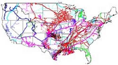 |
| Interstate Natural Gas Pipelines |
| Source: National Energy Technology Laboratory, DOE |
The interstate natural gas pipeline network transports processed natural gas from processing plants in producing regions to those areas with high natural gas requirements, particularly large, populated urban areas. As can be seen, the pipeline network extends across the entire country.
Interstate pipelines are the ‘highways’ of natural gas transmission. Natural gas that is transported through interstate pipelines travels at high pressure in the pipeline, at pressures anywhere from 200 to 1500 pounds per square inch (psi). This reduces the volume of the natural gas being transported (by up to 600 times), as well as propelling natural gas through the pipeline.
This section will cover the components of the interstate pipeline system, the construction of pipelines, and pipeline inspection and safety. For more information on interstate pipelines in general, click here to visit the website of the Interstate Natural Gas Association of America.
Pipeline Components
Interstate pipelines consist of a number of components that ensure the efficiency and reliability of a system that delivers such an important energy source year-round, twenty four hours a day, and includes a number of different components.
Transmission Pipes
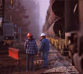 |
| Pipes in Transit |
| Source: Duke Energy Gas Transmission Canada |
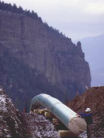
Transmission pipes can measure anywhere from 6 to 48 inches in diameter, depending on their function. Certain component pipe sections can even consist of small diameter pipe, as small as 0.5 inches in diameter. However, this small diameter pipe is usually used only in gathering and distribution systems. Mainline transmission pipes, the principle pipeline in a given system, are usually between 16 and 48 inches in diameter. Lateral pipelines, which deliver natural gas to or from the mainline, are typically between 6 and 16 inches in diameter. Most major interstate pipelines are between 24 and 36 inches in diameter. The actual pipeline itself, commonly called ‘line pipe’, consists of a strong carbon steel material, engineered to meet standards set by the American Petroleum Institute (API). In contrast, some distribution pipe is made of highly advanced plastic, because of the need for flexibility, versatility and the ease of replacement.
Transmission pipelines are produced in steel mills, which are sometimes specialized to produce only pipeline. There are two different production techniques, one for small diameter pipes and one for large diameter pipes. For large diameter pipes, from 20 to 42 inches in diameter, the pipes are produced from sheets of metal which are folded into a tube shape, with the ends welded together to form a pipe section. Small diameter pipe, on the other hand, can be produced seamlessly. This involves heating a metal bar to very high temperatures, then punching a hole through the middle of the bar to produce a hollow tube. In either case, the pipe is tested before being shipped from the steel mill, to ensure that it can meet the pressure and strength standards for transporting natural gas.
Line pipe is also covered with a specialized coating to ensure that it does not corrode once placed in the ground. The purpose of the coating is to protect the pipe from moisture, which causes corrosion and rusting. There are a number of different coating techniques. In the past, pipelines were coated with specialized coal tar enamel. Today, pipes are often protected with what is known as a fusion bond epoxy, which gives the pipe a noticeable light blue color. In addition, cathodic protection is often used; which is a technique of running an electric current through the pipe to ward off corrosion and rusting.
Compressor Stations
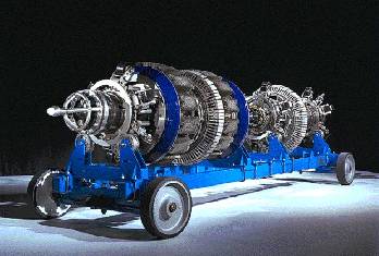
As mentioned, natural gas is highly pressurized as it travels through an interstate pipeline. To ensure that the natural gas flowing through any one pipeline remains pressurized, compression of this natural gas is required periodically along the pipe. This is accomplished by compressor stations, usually placed at 40 to 100 mile intervals along the pipeline. The natural gas enters the compressor station, where it is compressed by either a turbine, motor, or engine.
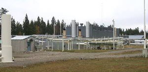 |
| A Compressor Station |
| Source: Duke Energy Gas Transmission Canada |
Turbine compressors gain their energy by using up a small proportion of the natural gas that they compress. The turbine itself serves to operate a centrifugal compressor, which contains a type of fan that compresses and pumps the natural gas through the pipeline. Some compressor stations are operated by using an electric motor to turn the same type of centrifugal compressor. This type of compression does not require the use of any of the natural gas from the pipe, however it does require a reliable source of electricity nearby. Reciprocating natural gas engines are also used to power some compressor stations. These engines resemble a very large automobile engine, and are powered by natural gas from the pipeline. The combustion of the natural gas powers pistons on the outside of the engine, which serves to compress the natural gas.
In addition to compressing natural gas, compressor stations also usually contain some type of liquid separator, much like the ones used to dehydrate natural gas during its processing. Usually, these separators consist of scrubbers and filters that capture any liquids or other unwanted particles from the natural gas in the pipeline. Although natural gas in pipelines is considered ‘dry’ gas, it is not uncommon for a certain amount of water and hydrocarbons to condense out of the gas stream while in transit. The liquid separators at compressor stations ensure that the natural gas in the pipeline is as pure as possible, and usually filter the gas prior to compression.
Metering Stations
In addition to compressing natural gas to reduce its volume and push it through the pipe, metering stations are placed periodically along interstate natural gas pipelines. These stations allow pipeline companies to monitor the natural gas in their pipes. Essentially, these metering stations measure the flow of gas along the pipeline, and allow pipeline companies to ‘track’ natural gas as it flows along the pipeline. These metering stations employ specialized meters to measure the natural gas as it flows through the pipeline, without impeding its movement.
Valves
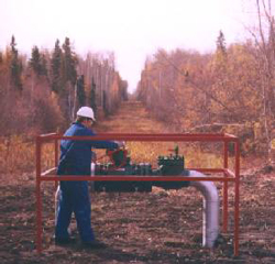 |
| A Ground Valve |
| Source: Duke Energy Gas Transmission Canada |
Interstate pipelines include a great number of valves along their entire length. These valves work like gateways; they are usually open and allow natural gas to flow freely, or they can be used to stop gas flow along a certain section of pipe. There are many reasons why a pipeline may need to restrict gas flow in certain areas. For example, if a section of pipe requires replacement or maintenance, valves on either end of that section of pipe can be closed to allow engineers and work crews safe access. These large valves can be placed every 5 to 20 miles along the pipeline, and are subject to regulation by safety codes.
Control Stations and SCADA Systems
Natural gas pipeline companies have customers on both ends of the pipeline – the producers and processors that input gas into the pipeline, and the consumers and local gas utilities that take gas out of the pipeline. In order to manage the natural gas that enters the pipeline, and to ensure that all customers receive timely delivery of their portion of this gas, sophisticated control systems are required to monitor the gas as it travels through all sections of what could be a very lengthy pipeline network. To accomplish this task of monitoring and controlling the natural gas that is traveling through the pipeline, centralized gas control stations collect, assimilate, and manage data received from monitoring and compressor stations all along the pipe.
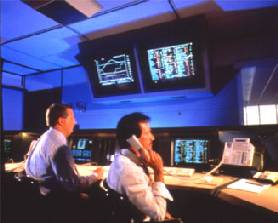 |
| Pipeline Control Station |
| Source: Duke Energy Gas Transmission Canada |
Most of the data that is received by a control station is provided by Supervisory Control and Data Acquisition (SCADA) systems. These systems are essentially sophisticated communications systems that take measurements and collect data along the pipeline (usually in a metering or compressor stations and valves) and transmit it to the centralized control station. Flow rate through the pipeline, operational status, pressure, and temperature readings may all be used to assess the status of the pipeline at any one time. These systems also work in real time, meaning that there is little lag time between the measurements taken along the pipeline and their transmission to the control station.
The data is relayed to a centralized control station, allowing pipeline engineers to know exactly what is happening along the pipeline at all times. This enables quick reactions to equipment malfunctions, leaks, or any other unusual activity along the pipeline. Some SCADA systems also incorporate the ability to remotely operate certain equipment along the pipeline, including compressor stations, allowing engineers in a centralized control center to immediately and easily adjust flow rates in the pipeline.
As natural gas use increases, so does the need to have transportation infrastructure in place to supply the increased demand. This means that pipeline companies are constantly assessing the flow of natural gas across the U.S., and building pipelines to allow transportation of natural gas to those areas that are underserved.
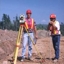 |
| Surveying the Right-of-Way |
| Source: Duke Energy Gas Transmission Canada |
Constructing natural gas pipelines requires a great deal of planning and preparation. In addition to actually building the pipeline, several permitting and regulatory processes must be completed. In many cases, prior to beginning the permitting and land access processes, natural gas pipeline companies prepare a feasibility analysis to ensure that an acceptable route for the pipeline exists that provides the least impact to the environment and public infrastructure already in place.
Assuming a pipeline company obtains all the required permits and satisfies all of the regulatory requirements, construction of the pipe may begin. Extensive surveying of the intended route is completed, both aerial and land based, to ensure that no surprises pop up during actual assembly of the pipeline.
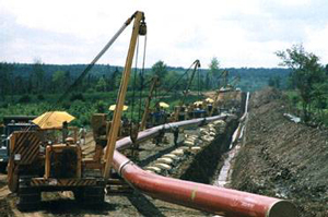
Installing a pipeline is much like an assembly line process, with sections of the pipeline being completed in stages. First, the path of the pipeline is cleared of all removable impediments, including trees, boulders, brush, and anything else that may prohibit the construction. Once the pipeline’s path has been cleared sufficiently to allow construction equipment to gain access, sections of pipes are laid out along the intended path, a process called ‘stringing’ the pipe. These pipe sections are commonly from 40 to 80 feet long, and are specific to their destination. That is, certain areas have different requirements for coating material and pipe thickness.
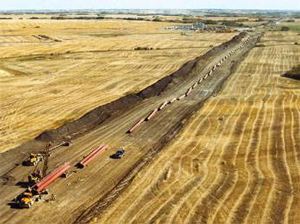 |
| ‘Stringing’ the Pipe |
| Source: Duke Energy Gas Transmission Canada |
Once the pipe is in place, trenches are dug alongside the laid out pipe. These trenches are typically five to six feet deep, as the regulations require the pipe to be at least 30 inches below the surface. In certain areas, however, including road crossings and bodies of water, the pipe is buried even deeper. Once the trenches are dug, the pipe is assembled and contoured. This includes welding the sections of pipe together into one continuous pipeline, and bending it slightly, if needed, to fit the contour of the pipeline’s path. Coating is applied to the ends of the pipes. The coating applied at a coating mill typically leaves the ends of the pipe clean, so as not to interfere with welding. Finally, the entire coating of the pipe is inspected to ensure that it is free from defects.
Once the pipe is welded, bent, coated, and inspected it can be lowered into the previously-dug trenches. This is done with specialized construction equipment acting to lift the pipe in a level manner and lower it into the trench. Once lowered into the ground, the trench is filled in carefully, to ensure that the pipe and its coating retain their integrity. The last step in pipeline construction is the hydrostatic test. This consists of running water, at pressures higher than will be needed for natural gas transportation, through the entire length of the pipe. This serves as a test to ensure that the pipeline is strong enough, and absent of any leaks of fissures, before natural gas is pumped through the pipeline.
 |
| Lowering Pipe |
| Source: Duke Energy Gas Transmission Canada |
Laying pipe across streams or rivers can be accomplished in one of two ways. Open cut crossing involves the digging of trenches on the floor of the river to house the pipe. When this is done, the pipe itself is usually fitted with a concrete casing, which both ensures that the pipe stays on the bottom of the river and adds an extra protective coating to prevent any natural gas leaks into the water. Alternatively, a form of directional drilling may be employed, in which a ‘tunnel’ is drilled under the river through which the pipe may be passed. The same techniques are used for road crossings – either an open trench is excavated across the road and replaced once the pipe is installed, or a tunnel may be drilled underneath the road.
Once the pipeline has been installed and covered, extensive efforts are taken to restore the pipeline’s pathway to its original state, or to mitigate any environmental or other impacts that may have occurred during the construction process. These steps often include replacing topsoil, fences, irrigation canals, and anything else that may have been removed or upset during the construction process. For more information on natural gas pipeline construction, visit the website of theInterstate Natural Gas Association of America.
Pipeline Inspection and Safety
 |
| Pig – Pipeline Inspection Tool |
| Source: Duke Energy Gas Transmission Canada |
In order to ensure the efficient and safe operation of the extensive network of natural gas pipelines, pipeline companies routinely inspect their pipelines for corrosion and defects. This is done through the use of sophisticated pieces of equipment known as ‘smart pigs.’ Smart pigs are intelligent robotic devices that are propelled down pipelines to evaluate the interior of the pipe. Smart pigs can test pipe thickness, and roundness, check for signs of corrosion, detect minute leaks, and any other defect along the interior of the pipeline that may either impede the flow of gas, or pose a potential safety risk to the operation of the pipeline. Sending a smart pig down a pipeline is fittingly known as ‘pigging’ the pipeline.
In addition to inspection with smart pigs, there are a number of safety precautions and procedures in place to minimize the risk of accidents. In fact, the transportation of natural gas is one of the safest ways of transporting energy, mostly due to the fact that the infrastructure is fixed, and buried underground. According to the Department of Transportation (DOT), pipelines are the safest method of transporting petroleum and natural gas. While there are in excess of 100 deaths per year associated with electric transmission lines, according to the DOT’s Office of Pipeline Safety in 2009, there were 0 deaths associated with transmission pipelines, and 10 deaths associated with distribution systems. To learn more about pipeline safety, visit the DOT’s Office of Pipeline Safety.
A few of the safety precautions associated with natural gas pipelines include:
- Aerial Patrols – Planes are used to ensure no construction activities are taking place too close to the route of the pipeline, particularly in residential areas. Unauthorized construction and digging is the primary threat to pipeline safety, according to INGAA
- Leak Detection – Natural gas detecting equipment is periodically used by pipeline personnel on the surface to check for leaks. This is especially important in areas where the natural gas is not odorized.
- Pipeline Markers – Signs on the surface above natural gas pipelines indicate the presence of underground pipelines to the public, to reduce the chance of any interference with the pipeline.
- Gas Sampling – Routine sampling of the natural gas in pipelines ensures its quality, and may also indicate corrosion of the interior of the pipeline, or the influx of contaminants.
- Preventative Maintenance – This involves the testing of valves and the removal of surface impediments to pipeline inspection.
- Emergency Response – Pipeline companies have extensive emergency response teams that train for the possibility of a wide range of potential accidents and emergencies.
- The One Call Program – All 50 states have instituted what is known as a ‘one call’ program, which provides excavators, construction crews, and anyone interested in digging into the ground around a pipeline with a single phone number that may be called when any excavation activity is planned. This call alerts the pipeline company, which may flag the area, or even send representatives to monitor the digging. The national 3-digit number for one call is “811.”
While large interstate natural gas pipelines transport natural gas from the processing regions to the consuming regions and may serve large wholesale users such as industrial or power generation customers directly, it is the distribution system that actually delivers natural gas to most retail customers, including residential natural gas users.